How House Wiring Works: A Guide to Home Electrical Wiring
Chameera Sampath · 10/18/2026
A guide to home wiring in the US: service, meter and panel, 120 V and 240 V circuits, room-by-room circuit requirements with NEC sections, wire gauge and breaker sizes, how NM-B cable is run, and the signs house wiring needs updating.
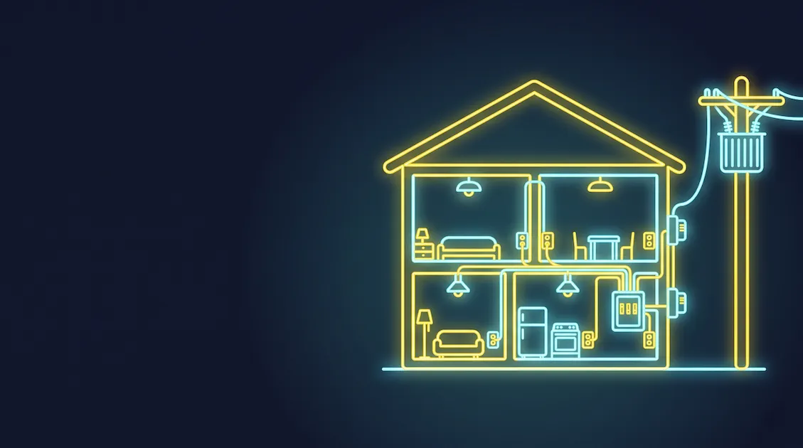
House wiring is the system of conductors, boxes, devices and protection that carries power from the utility's supply to every light, receptacle and appliance in a home. In the United States, home wiring follows a common pattern: a 120/240 V service enters through a meter to a main panel, where it is divided into branch circuits, each protected by a breaker and run through the house in cable or conduit. Residential electrical wiring, household wiring and home electrical wiring all describe the same system; this guide follows it from the utility to the last receptacle.
Quick answer. Utility transformer → service drop or lateral → meter → main panel → branch circuits → boxes → receptacles, switches and fixtures. Most houses have a 120/240 V single-phase service: 120 V for lighting and general receptacles, 240 V for ranges, dryers, water heaters and air conditioning.
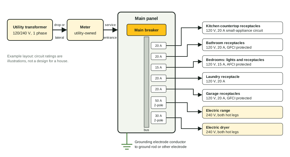
How residential house wiring is laid out. Circuit ratings in the diagram are examples, not a design for a particular house.
From the utility to the panel
- Utility transformer. A pole-mounted or pad-mounted transformer steps distribution voltage down to 120/240 V. One transformer often serves several houses.
- Service drop or lateral. Overhead conductors (a drop) or underground conductors (a lateral) carry two hot conductors and a neutral to the house. The utility owns and maintains this part.
- Service entrance and meter. The service entrance conductors run from the point of connection through the meter base. The utility's meter records the energy used.
- Service disconnect and main panel. The main breaker disconnects the whole house; for a one-family dwelling the service disconnecting means must be rated at least 100 A, three-wire, under NEC 230.79(C). Under the 2020 and later editions, NEC 230.85 also requires an emergency disconnect at a readily accessible outdoor location for one- and two-family dwellings, which is often met by a meter-main or an outdoor main breaker.
- Grounding electrode system. Ground rods, a concrete-encased electrode or a metal water pipe connect the electrical system to the earth at the service. See grounding and bonding.
120 volts and 240 volts
The service has two hot legs, each 120 V to the neutral and 240 V to each other. A single-pole breaker connects one hot leg and the neutral for 120 V circuits. A double-pole breaker connects both hot legs for 240 V circuits, used by large appliances because the same power at twice the voltage needs half the current. Some appliances, such as ranges and dryers, use both: 240 V for the heating elements and 120 V, through the neutral, for controls, lights and timers.
A multiwire branch circuit shares one neutral between two hot conductors on opposite legs. It saves a conductor, but the two breakers must disconnect together (a two-pole breaker or an identified handle tie) so that no one works on a circuit whose shared neutral is still carrying current from the other leg.
Inside the main panel
The main breaker feeds two bus bars, one per hot leg. Branch-circuit breakers clip onto the bus in alternating positions, which is why two adjacent spaces give 240 V. Two terminal bars complete the panel: the neutral bar, where the white conductors land, and the equipment grounding bar, where the bare or green conductors land.
At the service, and only there, the neutral and ground are bonded together by the main bonding jumper. Downstream, in a subpanel, neutrals and equipment grounds are kept on separate bars; NEC 250.24(A)(5) prohibits connecting the neutral to grounding on the load side of the service disconnect, because doing so would put normal neutral current on metal parts and grounding paths.
The panel's directory identifies each circuit. A complete, legible directory is required by NEC 408.4(A), and a panel schedule template turns it into a printed sheet for the panel door. For reading an existing panel, see how to read a circuit breaker panel.
Room-by-room circuits
The National Electrical Code sets minimum circuits and receptacles for dwellings in Article 210. The table summarizes the main requirements for each area; section numbers are from the 2023 NEC, and the edition and amendments adopted locally govern.
| Area | Circuits | Receptacles and protection | Lighting |
|---|---|---|---|
| Kitchen | At least two 20 A small-appliance branch circuits for countertop and dining receptacles, 210.11(C)(1) and 210.52(B) | Countertop receptacles so no point along the wall line is more than 24 in from one, 210.52(C); GFCI protection, 210.8(A) | Lighting outlet, 210.70(A) |
| Bathroom | At least one 20 A circuit for bathroom receptacles, 210.11(C)(3) | A receptacle within 3 ft of the outside edge of each basin, 210.52(D); GFCI protection, 210.8(A) | Lighting outlet, 210.70(A) |
| Laundry | At least one 20 A circuit for the laundry receptacle outlets, 210.11(C)(2) | Laundry receptacle, 210.52(F); GFCI protection in laundry areas, 210.8(A) | — |
| Bedrooms | General-purpose 15 A or 20 A circuits | Wall receptacles so no point along the floor line is more than 6 ft from one, 210.52(A); AFCI protection, 210.12(A) | Lighting outlet, 210.70(A) |
| Living and dining rooms | General-purpose 15 A or 20 A circuits | Same 6 ft spacing, 210.52(A); AFCI protection, 210.12(A) | Lighting outlet, 210.70(A) |
| Garage | At least one 20 A circuit for garage receptacles, 210.11(C)(4) | At least one receptacle in each vehicle bay, 210.52(G); GFCI protection, 210.8(A) | Lighting outlet, 210.70(A) |
| Outdoor | Usually a general-purpose circuit | Receptacles at the front and back of a one-family dwelling, accessible from grade, 210.52(E); GFCI protection, 210.8(A) | Lighting outlet at outdoor entrances, 210.70(A) |
Receptacles in dwelling units must be tamper-resistant under NEC 406.12, and outdoor receptacles in damp or wet locations must be weather-resistant types with suitable covers under 406.9. GFCI and AFCI devices are explained in GFCI vs AFCI.
Dedicated appliance circuits
Large or fixed appliances usually have their own circuits, sized from the nameplate and the manufacturer's instructions.
| Appliance | Typical supply | Notes |
|---|---|---|
| Electric range | 240 V, often 40 A or 50 A | Sized from the range's rating |
| Electric dryer | 240 V, often 30 A | Four-wire connection in new installations |
| Water heater | 240 V, often 30 A | Treated as a continuous load in sizing |
| Air conditioner or heat pump | 240 V, per nameplate | Uses the nameplate's minimum circuit ampacity and maximum overcurrent protection |
| EV charger | 240 V, per equipment | Treated as a continuous load in sizing |
| Dishwasher, disposal, microwave | 120 V, 15 A or 20 A | Often individual circuits |
These are common arrangements, not sizing rules; the breaker size calculator works through the sizing for a particular load.
Wire gauge and breaker size
Each conductor size has a largest breaker that may protect it. For the small copper conductors used in most house circuits, NEC 240.4(D) sets those limits directly. The wire size calculator checks ampacity and voltage drop for a particular circuit, and the standard breaker sizes page lists the ratings breakers are made in.
| Breaker | Copper conductor commonly used | Typical circuits |
|---|---|---|
| 15 A | 14 AWG | General lighting and receptacle circuits |
| 20 A | 12 AWG | Kitchen, bathroom, laundry and garage receptacles |
| 30 A | 10 AWG | Dryer, water heater, some air conditioners |
| 40 A | 8 AWG | Many electric ranges and cooktops |
| 50 A | 6 AWG | Larger ranges, some EV chargers |
Ampacity caveat. The table lists common pairings for copper conductors, not a sizing method. The allowable ampacity depends on the conductor's insulation temperature rating, the terminal ratings of the equipment (NEC 110.14(C)), the number of current-carrying conductors bundled together and the ambient temperature. NM-B cable is limited to the 60 °C ampacity column by NEC 334.80, aluminum conductors need larger sizes, and long runs may need larger conductors to limit voltage drop. The ampacity calculator applies the corrections and the voltage drop calculator checks long runs.
How wiring is run
- Nonmetallic-sheathed cable (NM-B, often called by the trade name Romex) is the most common method in houses: insulated hot and neutral conductors and a bare ground in a plastic jacket. Jacket colors indicate conductor size, and insulation colors identify each conductor's role; see the wire color code. NM cable is not permitted in wet or damp locations, which rules it out for outdoor runs and many slab-on-grade conduits.
- Through framing. Cable runs through holes bored near the center of studs and joists. Where the edge of a hole is less than 1¼ in from the face of the framing, a steel nail plate at least 1/16 in thick protects the cable from drywall screws and nails, under NEC 300.4(A)(1).
- Securing. NM cable is stapled or strapped within 12 in of every box and at intervals of no more than 4½ ft along its run, under NEC 334.30. Staples hold the cable without crushing the jacket.
- At the box. Each cable enters the box through a clamp or connector, and at least 6 in of free conductor is left in the box for making connections, under NEC 300.14.
- Metal-clad cable (MC) has an interlocked metal armor and is used where physical protection is needed or required.
- Conduit (EMT, PVC, rigid) is a pipe through which individual conductors are pulled; common in garages, basements, outdoors and commercial work.
- UF cable is rated for direct burial underground.
Boxes and devices
Every splice, receptacle, switch and fixture sits in a box, which contains the connections and any heat or sparks. Each box must be large enough for the conductors, devices and clamps inside it under NEC 314.16; the box fill calculator works out the required volume. Ceiling boxes that support fans must be listed for fan support. Switch locations, receptacle spacing and lighting outlets for a whole house are easiest to plan on a drawing; the electrical plan maker places them on a floor plan with a symbol legend.
How a new house is wired
- Planning and load calculation set the service size and circuit layout; see the residential load calculation guide.
- Permit from the local building department.
- Rough-in: boxes are mounted, holes are bored and cable is run and stapled through framing before walls are closed.
- Rough-in inspection by the authority having jurisdiction, with the cable, boxes and protection plates still visible.
- Trim-out: after drywall, devices, fixtures and breakers are installed and the panel directory is filled in.
- Final inspection, then the utility connects or releases the service.
Signs that wiring needs updating
Wiring rarely fails all at once; it shows symptoms first. Any of these is a reason for an evaluation by a licensed electrician:
- Breakers that trip repeatedly, or fuses that blow; see why a circuit breaker keeps tripping.
- Receptacles, switch plates or the panel cover that feel warm, are discolored or smell of burning plastic.
- Lights that flicker or dim when an appliance starts, beyond a brief dip.
- Two-prong receptacles with no equipment grounding conductor, or three-prong receptacles installed on ungrounded wiring.
- Knob-and-tube wiring, cloth-insulated cable or aluminum branch-circuit wiring.
- A fuse panel, a panel with no spaces left, or a service too small for added loads such as an EV charger or heat pump.
- Extension cords and power strips in permanent use because a room has too few receptacles.
- A tingle or shock from an appliance, fixture or faucet.
Wiring in older houses
Houses built before the 1960s may contain knob-and-tube wiring, which has no ground conductor, or two-wire cable without a ground. Some houses from the mid-1960s to mid-1970s have aluminum branch-circuit wiring, whose connections need specific devices or repair methods. Fuse panels and undersized services are also common. Older systems are judged by their condition and by the loads now connected to them, not by age alone.
Frequently asked questions
What voltage is house wiring in the US? 120/240 V single phase: 120 V for most receptacles and lighting, 240 V for large appliances.
What wire is used for house wiring? Most often NM-B copper cable: 14 AWG for 15 A circuits, 12 AWG for 20 A circuits, and larger for 240 V appliances, subject to the ampacity checks above.
How many circuits does a house need? It depends on the house. The NEC sets minimums, including two kitchen small-appliance circuits and one circuit each for the laundry, bathroom receptacles and garage receptacles,; the total depends on the size of the house, its appliances and its load calculation.
What size electrical service does a house need? At least 100 A for a one-family dwelling under NEC 230.79(C); the actual size comes from a load calculation under NEC Article 220. Houses with electric heat, an electric range, a heat pump or an EV charger often need a larger service, commonly 200 A.
Can 14-gauge wire be used on a 20 A circuit? No. NEC 240.4(D) limits 14 AWG copper to 15 A overcurrent protection. A 20 A circuit needs at least 12 AWG copper.
Can homeowners do their own wiring? Some jurisdictions allow homeowners to do electrical work on their own home with a permit and inspection; others do not. The local building department sets the rule.
How long does house wiring last? Modern copper NM cable can last many decades; insulation, connections and devices are what age. Older systems should be evaluated rather than judged by age alone.
What is the difference between house wiring and an electrical plan? House wiring is the installed system. An electrical plan is the drawing that shows where its receptacles, switches, lights and circuits go; it is made before rough-in and used for the permit.
Related guides and tools
- Electrical plan maker: lay out receptacles, switches and lights on a floor plan.
- Panel schedule template: a printable circuit directory for the panel door.
- Wire size calculator: minimum wire size by ampacity and voltage drop.
- Wire size by breaker rating: 20 A, 30 A, 40 A, 50 A, 60 A, 100 A, 150 A and 200 A.
- AWG wire gauge chart: diameter, area and resistance of each gauge.
- Electrical wire color code: what each conductor and cable jacket color means.
- How to read a circuit breaker panel: breakers, labels and ratings.
Scope
This article describes residential wiring in the United States under the National Electrical Code. Electrical installation and alterations should be carried out under permit by, or under the supervision of, a licensed electrician.
Written by Chameera Sampath. Not yet reviewed by a licensed electrician — see the methodology page. To report an error, use the contact page.